ALEXANDER CUBELLIS
Truss Bridge Design Request for Proposal


Scoping the Problem:
Given the time constraints our group developed a set of high level objectives that we ordered in rank of importance as follows:
-
Making the bridge as safe as possible
-
Making the design inexpensive
-
Developing an aesthetically pleasing design
In addition, our group developed a list of DFX’s that would allow us to meet the requirements of the stakeholders (as specified in the RFP document). These DFX’s include:
-
Design for Safety
-
Design for Constructability
-
Design for Effectiveness
-
Design for Aesthetics
The Iterative Process and Quantitative Analysis Methods:
Our group began the decision-making process by looking at reference truss designs. Some of the original designs in contention included the following:


Howard Duan, Engineering Science 1T7
The engineering design process shown here was largely inspired by
the experiences that my team and I went through as we tried to develop
a solution to the candidate problem described in the abstract to the right:
I will explain how my engineering design process was used to
address the problem described in the abstract. Please also peruse the
RFP that my team drafted to the left, as I will be referencing parts of the
RFP as I describe how my engineering process was refined.
RFP? – Recognition of Need:
Our team was in the unique position of being both the team that crafted the request for proposal, and the team that responded to the proposal. As such we developed an intimate connection with the candidate community and a thorough understanding of the problem. We were able to identify the need by engaging with the stakeholders, namely Mr. Strickland, the Director of Operations at The Scott Mission, and gained a first-hand account of the occupational health and safety concerns that the staff faces when processing donations.
Reframe or Redefine/Scoping:
In the preliminary stages of the design process, our team was convinced that given the nature of the problem, it would be too difficult to handle donations processing where goods are transported from the inside of the delivery truck into the chute. As such, our team focused instead on developing a solution to address manual materials handling at the end of the conveyor.
Conceptualization/Prototyping:
As our team began to develop our preliminary design, we tried to eliminate MMH by creating an environment that permitted the staff to perform lifting tasks in accordance with the Snook Ideal standard for lifting. This “ideal lifting and pushing standard” provides a recommended lifting/pushing height depending on the height of the individual and the weight of the mass to be moved. Therefore we considered devising a pallet system that could be used at the end of the conveyor with an adjustable height so instead of lifting boxes off of the conveyor they could instead be pushed down the conveyor and onto a waiting pallet. (See the problem areas 1 and 2 above).
One of my teammates also suggested developing a modular ramp that could be used at different points in the donations process. However this idea was not well-received by the group as the idea was not communicated effectively and it seemed unfeasible at the time. (In hindsight, I now recognize the importance of not discounting the input of others even when what they are saying seems unreasonable. This modular ramp idea would actually become something a variation of our final solution.)
As our team continued to develop this idea, we were approached by our point person and we were informed that we should try to diversify our solution set. As such we tried to apply divergent and convergent methods to do so. One particularly effective method we applied was the SIT (Systematic Inventive Thinking) method where designers must restrain themselves to using only the information and resources that are provided in the context of the outlined problem and not to draw upon extraneous ideas or resources. As such this forced us to think within the confines of the solutions that we had already developed.
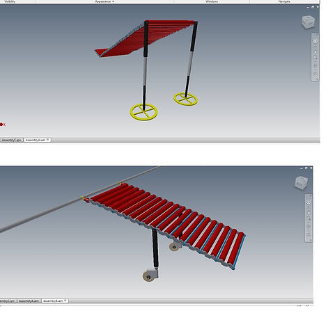
The key turning point in our design process was when we recognized that the modular ramp could be used if it was comprised of individual repeating units (See the diagram below).
Each of the red rollers shown at the right can be easily taken apart or put together due to their modular design. As such the same conveyor belt system could be used to unload goods from the truck into the chute and off the end of the conveyor onto waiting pallets.
The rollers can effectively be "spooled" under the existing roller belt (see the star in the poster) and then unravelled into the waiting truck.

Howard Duan, Engineering Science 1T7
The stands are then locked in place (figure to the right) so that the boxes can be slid down the length of the roller and into the basement.
The second modification that was made was to outfit the exisiting conveyor belt in the basement with a metal bar. This would allow the roller to be slid along the length of the existing conveyor (using the wheel attachment shown). The boxes would then be pushed down the roller onto the waiting pallet. As such this design greatly reduces MMH.
Overall I am very proud of the design that my team Howard Duan, William Eddie, and Xiuyian Sule Yu developed.

Howard Duan, Engineering Science 1T7
Howard Duan, Engineering Science 1T7